Large Dazzling Chrismas Coupons on PCBWay: https://www.pcbway.com/activity/chris...
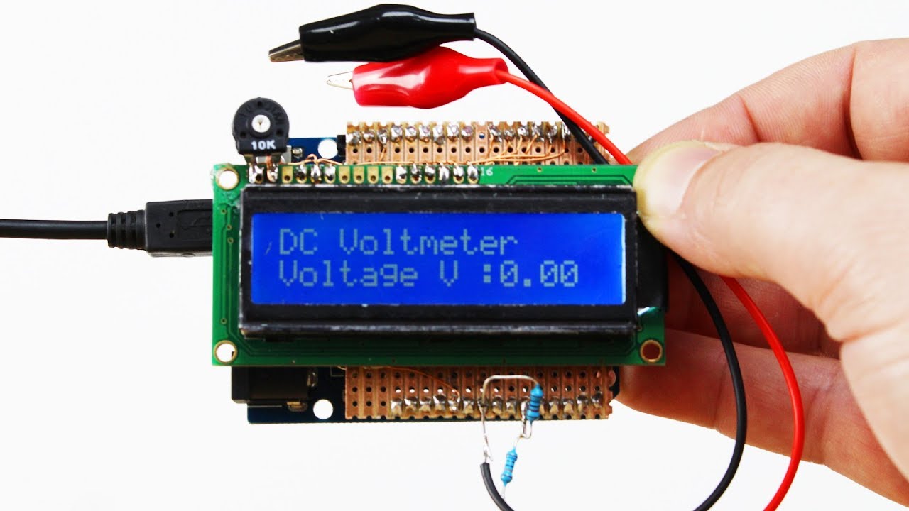
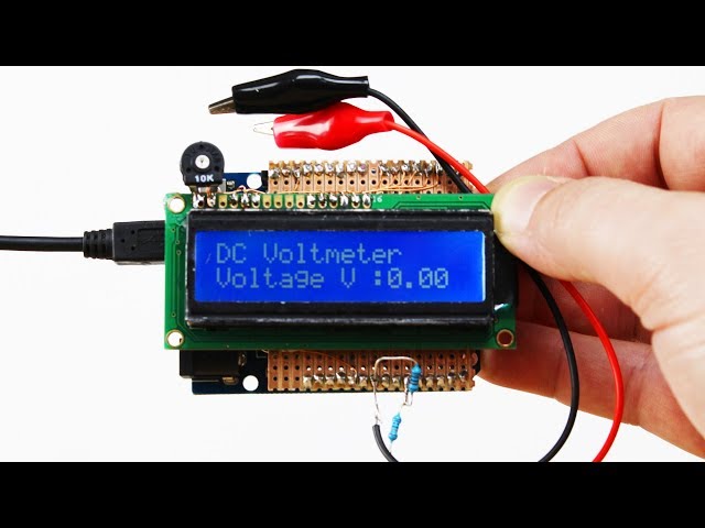
Connections between lcd display and arduino board:
* R1 100kohm Resistor
* R2 10kohm Resistor
- LCD RS pin to digital pin 2
- LCD Enable pin to digital pin 3
- LCD D4 pin to digital pin 4
-LCD D5 pin to digital pin 5
- LCD D6 pin to digital pin 6
- LCD D7 pin to digital pin 7
- LCD R/W pin to ground
- LCD VSS pin to ground
- LCD VCC pin to 5V
- 10K resistor:
- ends to +5V and ground
- wiper to LCD VO pin (pin 3)
Thanks to Razib Shahadat for sharing
Schematic and source code download:https://drive.google.com/file/d/167Ee...
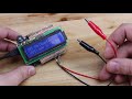
How to Make a Digital Voltmeter using Arduino ─ Hacktuber

<style>.embed-container { position: relative; padding-bottom: 56.25%; height: 0; overflow: hidden; max-width: 100%; } .embed-container iframe, .embed-container object, .embed-container embed { position: absolute; top: 0; left: 0; width: 100%; height: 100%; }</style><div class="embed-container"><iframe src="https://www.youtube.com/embed/MiBeIjZO0xo" frameborder="0" allowfullscreen></iframe></div>